The Auto-bug Keyer Mark II with Eight Message Memories
The auto-bug keyer, or electronic bug key, allows automatic or manually controlled variable length dashes while it adjusts the dots and spaces automatically. The original version of the keyer was described in a QST article.1 It was similar to the Mark II, but contained provision for only four message memories.
Features of Mark II
I received many inquiries and requests for the program file following the publication of the original article. This led me to believe that there were many hams interested in the original auto-bug keyer. Since that time, I have upgraded it to the auto-bug keyer mark II. The added features of the updated version are:
- Eight message memories.
- Added simple functions.
- A simpler circuit.
The following features from the original remain:
- Four operation modes -- iambic, auto-bug, ultimatic and sideswiper.
- Message memory is not volatile and can be used in any operational modes.
- Low power consumption.
Eight Message Memories by Four Push Buttons
Having additional channels of message memory is very helpful for many kinds of operation. The down side is that it is not easy for me to remember which memory channel has which message. I decided to use a switch to shift one set of four memories to other spaces in the memory IC. When the operating style changes, as in going from normal operation to contest mode, or from ragchewing to DXing, for example, you can shift to a different set of memories.
Message memory can store the signal as you operate, in the current operation mode. Iambic signals are stored as they are sent, as are variable length auto-bug signals. The recorded dash length can vary, according to your fist, from the length of a single dot to about eight dots in length compared to the automatically generated three-dot dash. Spaces can be recorded from as short as a single dot (normal) to a duration of 40 dots.
Functions
The included functions are described below:
- Demonstration mode -- The control signals of the keyer, such as BT and AR normally only beep in the monitor speaker and don't come to the output of the keyer. This helps the operation with headphones.
- Automatic CQ -- The memory switch for channel 2 is used to initiate an automatic CQ. A single pattern of CQ three times, followed by call sign and AR and K. A call sign should be recorded in advance to use this function.
- Repeat mode -- Messages are replayed repeatedly until a stop request is received. The interval is the same length as the space at the end of the message you recorded.
- Channel four and channel eight initiate repeat mode -- only channel four and channel eight can be used for repeat mode.
- Auto-bug mode -- Auto CQ and the control signals such as AR, are sent in auto-bug mode.
- Call sign input -- Input your call sign to use it in auto CQ mode. You can use any operational mode. The call sign will be played back as you recorded it.
- Ultimatic mode -- If you switch the mode to iambic, the operational mode will be ultimatic. Users do not switch the operational mode often. So, this became the software switch as well as the next sideswiper mode.
- Sideswiper mode -- If you switch the mode to auto bug, the operating mode will be sideswiper. With this mode also, variable dashes and the space adjustment apply.
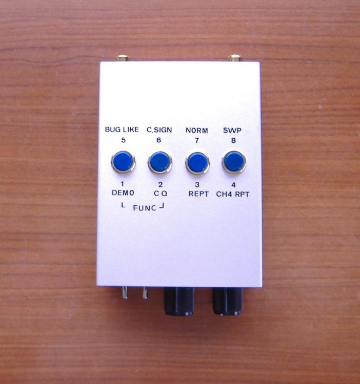
It is impossible for me to remember all the assignment of the functions. So, take the look at Figure 1 to get the idea. The instant lettering allows me to forget the instructions.
Circuit Description
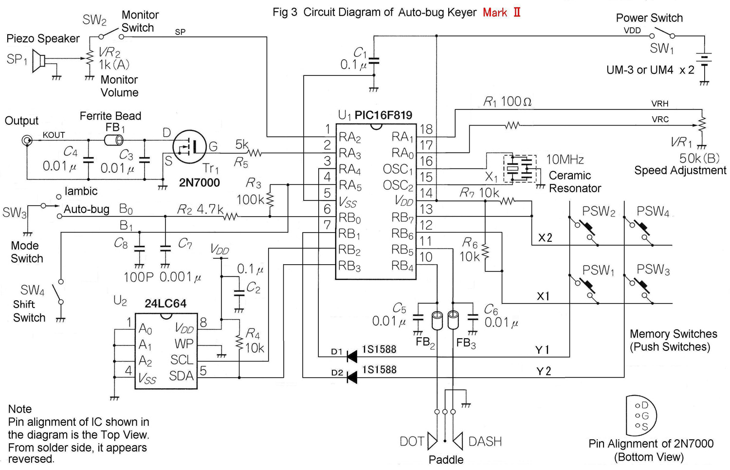
Figure 3 shows the circuit diagram. The circuit is a little simpler than the last version. A gate IC for channel selection is replaced by a switch matrix. The MODE switch is also simpler. The PIC microcomputer and the memory IC are the same as in the original version. It is nice that a higher capacity PIC is not necessary for this system upgrade.
S4 is the SHIFT switch for the memory. When you push any memory switch, the PIC repeats alternatively trying to charge C8 and checking the voltage, at high speed. If the switch is OFF, C8 will be charged, but if it is ON it will not charge. Thus the PIC knows if this switch is on or off. It is just enough that the switch be turned on for a moment. Therefore, the switch may be either a toggle switch or a momentary contact push button. The latter is similar to a keyboard shift key.
It is important to use sockets for ICs. They will allow for easy firmware updating and avoid static problems until ICs are mounted at the end of the assembly process. Potentiometer R9 controls the keying speed. Any value of resistance within the range 10,000 ohms to 100,000 ohms can be used, but a linear type should be selected. R8, on the other hand, is best if an audio taper. FB1 should be FB-101 or a similar sized ferrite bead. I once suffered FET damage by the back electromotive force when I used a larger size, an FB-801.
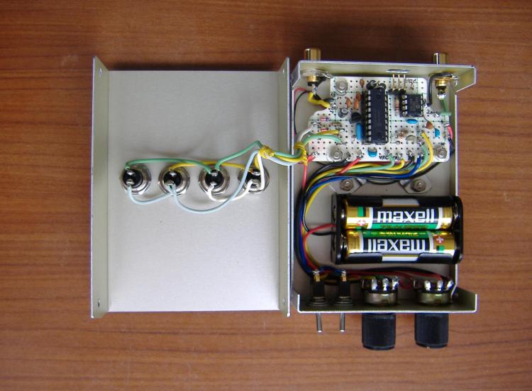
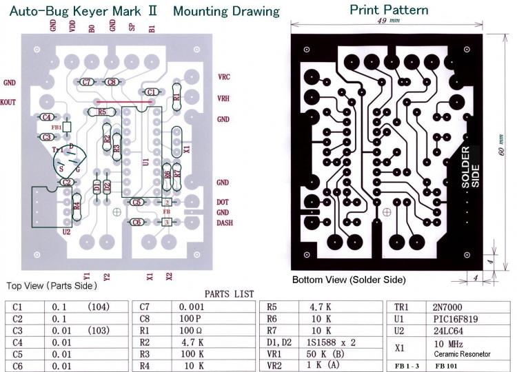
Figure 2 shows the PCB pattern from the parts side of the board and the parts mounting detail. The size of the pattern is 49 × 60 mm. I used a universal board to minimize the size. I also cut the corner off the board to squeeze out the space for the connector. Refer to Figure 4 for the inside configuration.
Real Time Mode Operation
Connect the batteries and plug in your paddle. The paddle may be either the single or double lever type. But of course, iambic mode will not really work with a single lever paddle. Turn S1 and S2 on and set R9 (SPD) and R8 (MON) at the center position.
First, set S3 to the iambic position, and try keying. Then check the speed control by varying R9. Next, turn S3 to AUTO-BUG and try this mode. Check to make sure the dashes are manual and of variable length. Dots should be automatic and spaces should follow your keying even with very short spacing. If you do not notice the expected adjustment, turn R9 left to set the speed to minimum and try again. You will soon understand what the auto-bug keyer is doing. After some short practice, you will be a proficient bug operator.
Message Memory
Turn S4 off and push any of memory switches S5 to S8 for about 2 seconds. Then the monitor beeps R and BT. R will be at fixed speed and BT at the speed set by R9. Release the switch to stop the beeps. The previous record, if any, is cancelled by this.
Then manipulate the paddle to record your message in any operation mode. The signal is recorded at the mode in operation when you pushed the memory switch. When you finish the message, push the memory switch briefly. Then, the monitor beeps AR and the keyer finishes the recording. The last space after the end of the message is cancelled. If there is no message recorded, the monitor just beeps the letter T.
If the repeat mode is set, the last space after the message is recorded until the memory switch is pushed is the intermessage space. At the same time it will be the time lag to be back to the real time mode. The recorded message remains in the memory even after the keyer is turned off. To replay, push the memory switch briefly. The stored message from the selected channel will be sent out in the same mode it was recorded in, but at the current speed setting. You can stop replaying by pushing the dash paddle.
Turning S4, the SHIFT switch, ON provides an additional four memory channels. S5 to S8 will enable channel five to eight. The maximum length of stored message varies by the operational mode. Typically, each channel will store at least 200 characters.
The current consumption is about 2.5 mA with the volume of the monitor at maximum. The consumption drops to 1.5 mA with the monitor off and to less than 10 µA while the keyer is idling.
Using Other Functions
To initiate the setting of the functions described above, push S5 and S6 together for 2 seconds. The monitor should beep ?. Then, push the PSW of the number corresponding to the item number described in the functions section for about 2 seconds. Turn the SHIFT switch OFF for items one to four and turn it on for item five to eight. It beeps R and the function is set. For instance, if you push S6 with SHIFT switch OFF after ?, auto CQ will be set and S6 will be the start switch of CQ while the SHIFT switch is OFF.
Pushing the SHIFT switch briefly after ?, the monitor beeps N and the corresponding function will be canceled.
There is an exception. S6 with the shift switch on will initiate the input of your call sign, by either a long or brief push. After the beep of BT, you can manipulate the paddle and record your call sign. Then push any PSW to finish recording.
The function setting and your call sign are recorded in the non-volatile memory and will remain after the power is turned off. When you want to cancel all the functions, turn the power on with PSW pushed. The monitor beeps R and all will be reset.
The object hex file to program a PIC16F819 will be provided by e-mail, for your personal use. A programmed PIC processor is also available. For any inquiries, just send an e-mail to Taka’s address at the beginning of this article.
Epilogue
It was a pleasant surprise to hear from the US that an auto-bug keyer became a Father's Day present. In Japan, I have received many impressive notes from users including some from hams "trying to refresh their brains to come back to CW with this keyer." How nice!
Taka K. Shimazu received his first Amateur Radio license in 1965 and upgraded to the (Japanese) First-class license in 1975. While working for his employer in the US in 1986 he held the call KE6QO. Business travel took him to Singapore from 2000 to 2003 where he operated as 9V1DJ. He enjoys building his own transceivers, transverters, linear amplifiers and peripheral equipment including keyers. Some of his home brew equipment still uses tubes. The auto-bug is the nineteenth keyer he has built since 1968.
Taka's professional life is as an environmental engineer. Sometimes he has had the opportunity to work in overseas assignments on projects such as air pollution control facilities and wastewater treatment plants. Amateur Radio and local hams have always made the stay more enjoyable. You may contact Taka at 10-36 Kizuri 3-chome, Higashiosaka, Osaka 577-0827, Japan.
1T.Shimazu, "Auto-bug Keyer with Message Memory," QST, May 2006, pp 36-38.
Taka K. Shimazu, JA3KAB
Photo Gallery
-
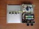 Figure 4. Inside ...
-
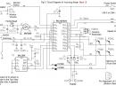 Figure 3. Circuit...
-
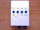 Figure 1. Top vie...
-
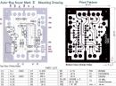 Figure 2. Mountin...
Back


